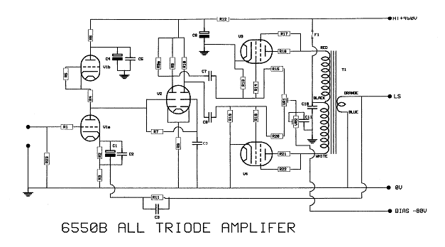
20W All Triode AmplifierAmplifier Circuit Diagrams - PLEASE NOTETo build these circuits, you should be an EXPERIENCED ELECTRONIC TECHNICIAN. The circuit diagrams etc are believed to be good quality and correct. However, please note that several different people have built amplifiers for us in the past (mainly in the 1990s), using valves like S11E12, TT21, E180CC etc. Since most of those people are now retired, you are free to use this data as a free gift, in good faith for you, an EXPERIENCED ELECTRONIC TECHNICIAN, to study and aid development of YOUR OWN IDEAS. The data you see in the following pages are therefore intended to be a GUIDE ONLY - not step-by-step instructions. We try to be helpful but advice, available by email only, is limited. We cannot advise about amplifiers by telephone. Parts List
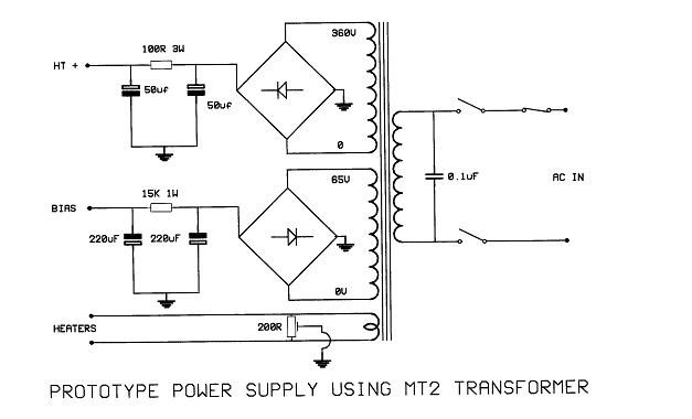
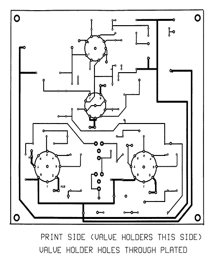
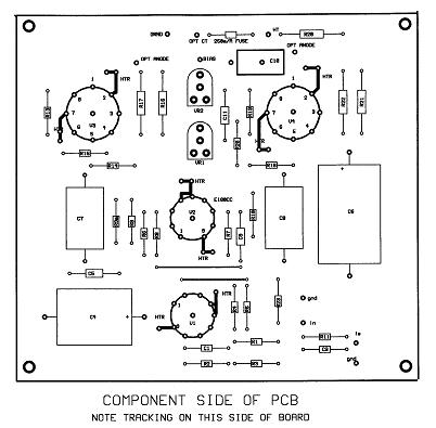
NotesTo set the quiescent current in the output valves, remove the 250m/A fuse and connect a meter in itís place, set VR2 to give 110m/A. To balance the output valves, connect a voltmeter between the anodes and adjust VR1 for zero volts. Printed Circuit Board NotesThe prototype was constructed on double sided fibreglass PCB. The heater pins on the valves have plated through holes or through connections and all the heater wiring is offboard twisted PVC covered hook-up wire. The valveholders are mounted on the same side as the print, opposite to all the components. The valveholders are aligned with clearance holes in the chassis. Connections to the power supply, input, feedback and output transformer are by PCB pin connectors. Power Supply NotesThe prototype amplifier uses a wire ended output transformer with the ratings shown above, using solid state bridge rectifiers for both HT and bias supplies.
|
||||||||||||||||||||||||||||||||||||||||||||||||||||||||||||||||||||||||||||||||||||||||||||||||||||||||||||||||||||||||||


|
|
19 April 2024
|
Quick links |
|
Free Downloads |
|
|

| Notice
board |


