Billington Export Ltd logo
Information Banner


Tel: +44 (0)1403 784961
Email: sales@bel-tubes.co.uk

Enter a product code then click 'Go'   
23 April 2024 


Quick links
 

Free Downloads


Click here to get Adobe Reader


ECC83 Mullard tube/ 12AX7 valve data/ 12AX7 RCA tube

Click here to add this valve to your shopping basket

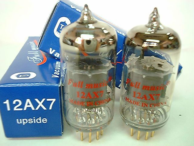
Photo of two ECC83/12AX7 High-MU A.F. Double Triodes shown with packaging boxes

General Information

An miniature indirectly heated twin triode. Each triode is a separate unit, the heaters being the only common connection. As a result it is possible to use each unit for different functions or both in cascade. The feature of a heater tap allows for both A.C. & D.C. supply.

CATHODE Indirectly heated by A.C. or D.C.; series or parallel supply

                                           Series - pins 9-(4+5)             parallel - pins 4+5

Heater Voltage                                       12.6                                         6.3                           V

Heater current                                       150                                          300                          mA


Max D.C. Heater –Cathode Potential                   250                          V


MAXIMUM RATINGS (each triode unit)

Maximum anode voltage                                         Va            300                          V

Maximum anode dissipation                                   Wa          1.0                           W

Maximum Cathode Current                                  Ik             8                              mA

Maximum  Negative Control Grid Voltage           -Vg           50                            V

Maximum Positive Control Grid Voltage              Vg            0                              V                             


TYPICAL OPERATION CONDITIONS & CHARACTERISTICS

Anode Voltage                        Va                            100                          250          V

Grid Voltage                           Vg                            -1.0                          -2.0          V

Anode Current                      Ia                             0.5                           1.2           mA

Transconductance                  S                              1.25                         1.6           mA/V

Amplification Factor               µ                              100                          100

Internal resistance                  Ri                             80                            62.5         KΩ


DIMENSIONS

Maximum overall length                                                         55.6                         mm

Maximum seated height                                                          49.2                         mm

Maximum diameter                                                              22.2                         mm

Base                                                                         Noval B9A


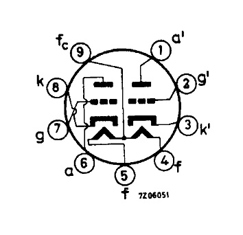
BASE CONNECTIONS

Pin1         Anode     )

Pin2         Grid        )---- Second Triode Unit

Pin3         Cathode  )


Pin4         Heater

Pin5         Heater


Pin6         Anode     )

Pin7         Grid        )-----First Triode Unit

Pin8         Cathode  )


Pin9         Heater Tap


Illustration showing  ECC83/12AX7 base connections

Click here to add this valve to your shopping basket


CAPACITIES (Approx) (Measured without shield)

First triode Unit             Second Triode Unit


Grid – Anode                                      1.7                           1.7           pF

Grid – Cathode                                    1.6                           1.6           pF

Grid – Cathode                                    0.46                         0.34         pF

Heater – Cathode                                  4.0                           4.0           pF


CAPACITIES (Approx)  cont.


Grid 1 – Anode 2                                            0.03         pF

Grid 2-    Anode 1                                          0.06         pF

Anode 1 – Anode2                                            0.75         pF max.

Grid 1 – Grid 2                                             0.008       pF max.


OPERATING CHARACTERISTICS


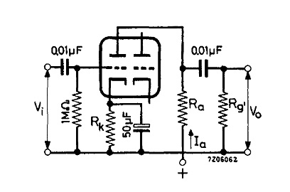
As A.F. Amplifier – (ONE UNIT)


Supply Voltage                                       Vb            200          250          300          350          400          V

Anode Resistor                                      Ra            47           47           47           47           47          kΩ

Grid Resistor next stage                        Rg’           150          150          150          150          150          k>Ω

Cathode Resistor                                   Rk           1500        1200        1000        820          680          Ω

Anode Current                                      Ia           0.86         1.18         1.55         1.98         2.45         mA

Voltage Gain                                         Vo/Vi  34         37.5        40          42.5         44            -

Output Voltage (Ig=0.3µA)                    Vo            18           23          26        33        37         VRMS

Total Distortion                                     dtot 8.5          7.0          5.0          4.4          3.6           %<


Supply Voltage                                       Vb            200          250          300          350          400          V

Anode Resistor                                      Ra            100          100          100          100          100          k>Ω

Grid Resistor next stage                        Rg’           330          330          330          330          330          kΩ

Cathode Resistor                                   Rk           1800        1500        1200        1000        820          Ω

Anode Current                                      Ia            0.65         0.86         1.11         1.40         1.72         mA

Voltage Gain                                        Vo/Vi  50          54.5         57           61           63           -

Output Voltage (Ig=0.3µA)                    Vo            20          26            30           36           38         VRMS

Total Distortion                                    dtot 4.8          3.9          2.7          2.2          1.7           %


Supply Voltage                                      Vb            200          250          300          350          400          V

Anode Resistor                                      Ra            220          220          220          220          220          kΩ

Grid Resistor next stage                        Rg’            680          680          680          680          680          kΩ

Cathode Resistor                                   Rk            3.3          2.7          2.2          1.5          1.2       kΩ

Anode Current                                      Ia             0.36         0.48         0.63         0.85         1.02         mA

Voltage Gain                                       Vo/Vi    56          66.5         72           75.5         76.5         -

Output Voltage (Ig=0.3µA)                   Vo            24          28           36           37           38           V RMS

Total Distortion                                   dtot 4.6           3.4         2.6          1.6          1.1           %


Technical illustration showing operating characteristics of  ECC83/12AX7 as A.F. Amplifier - (One Unit)


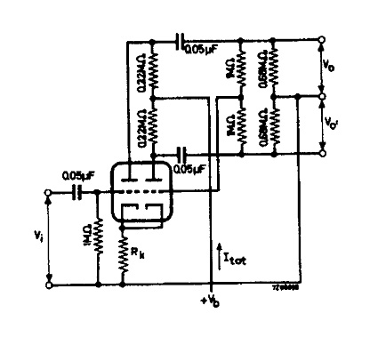
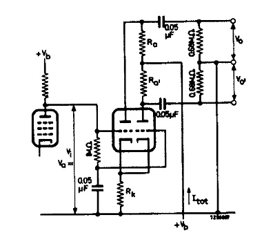
As Phase Inverter


Supply Voltage                                                     Vb            250          350          V

Cathode Resistor                                                   Rk            1200         820          Ω

Total Current                                                      Itot          1.08         1.7           mA

Voltage Gain                                                       Vo/Vi  58            62            -

Output Voltage (Ig=0.3µA)                                   Vo            35            45           V RMS

Total Distortion                                                   dtot 5.5          3.5           %


Technical illustration showing operating characteristics of  ECC83/12AX7 as Phase Inverter


Supply Voltage                                                     Vb            250          350          V

Anode Voltage                                                      Va 65            90            V

Cathode Resistor                                                   Rk            68            82            kΩ

Total Current                                                      Itot          1.0           1.2           mA

Anode Resistor                                                     Ra            100          150          kΩ

Anode Resistor                                                     Ra’           100          150          kΩ

Voltage Gain                                                       Vo/Vi   25           27            -

Output Voltage (Ig=0.3µA)                                   Vo            20           35            V RMS

Total Distortion                                                   dtot 1.8           1.8           %
 

Technical illustration showing operating characteristics of  ECC83/12AX7 as Phase Inverter

Click here to add this valve to your shopping basket

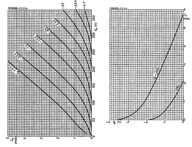
Charts showing technical data for the ECC83/12AX7 High-MU A.F. Double Triode


Securitymetrics Logo

Notice board


Click here to view photos of the Billington Export Team


Click here to view our special offers!


Click here to get our stock list

Click here for information about our minimum order requirement

Click here for information about items that we want